
Description
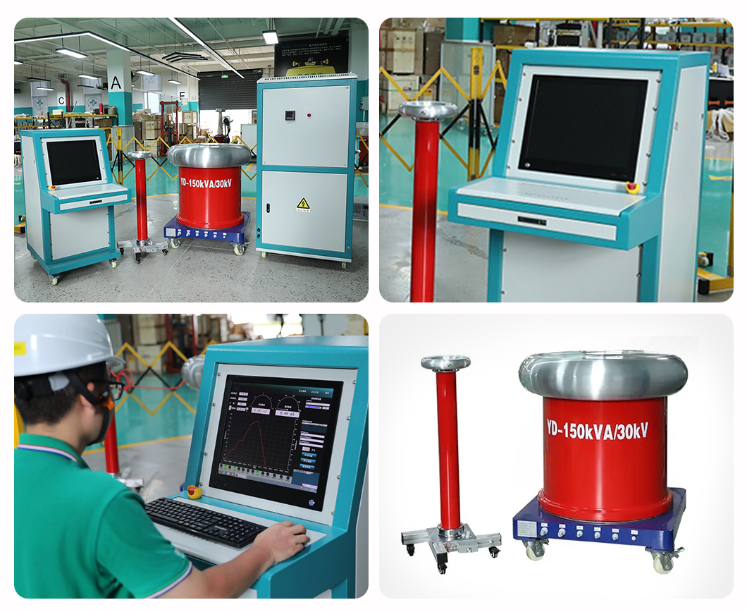
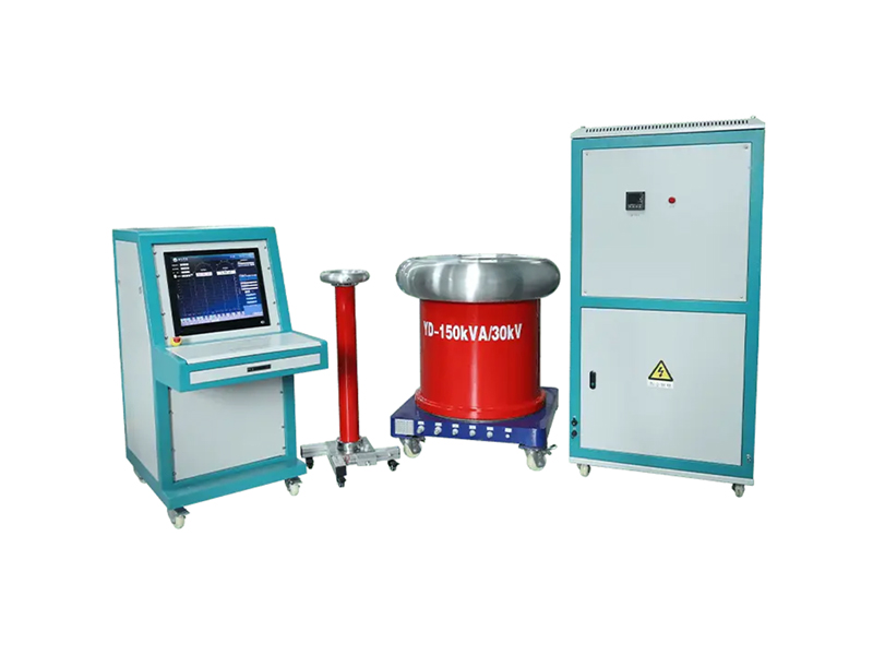
The insulation withstand voltage test device adopts PLC controller technology, 2.4G ISM networking technology, and an excellent human-machine interface, making it easy and convenient for you to use. It can be used to perform insulation strength tests on various electrical products, electrical components, and insulating materials under specified voltages to assess the insulation level of products, detect insulation defects in the test specimens, and measure overvoltage capability.
Features
1. Standard configuration includes a 19-inch integrated industrial computer and a programmable logic controller (PLC) for automated control.
2. Synchronous isolated acquisition of high-voltage, high-voltage, low-voltage, and low-voltage current, utilizing high-precision sensors and high-performance acquisition chips.
3. Independent interface display of high-voltage, high-voltage, low-voltage, low-voltage current, milliammeter leakage current, time, and withstand voltage results; dynamic display of the high-voltage curve for clear and intuitive readings.
4. Comprehensive overvoltage, overcurrent, and flashover protection; self-setting of output voltage, high-voltage current upper limit (optional intelligent high-current meter monitoring and tripping), milliammeter protection current, and timing time. Low-voltage current protection (hardware pre-set).
5. The system includes four test items: insulating gloves (boots), insulating rods, insulating mats, and power frequency withstand voltage. Each test item has an independent interface display.
6. During the test phase, saved test item parameters can be selected, or parameters can be reset.
7. Approximation voltage regulation algorithm; automatic withstand voltage timing after reaching the set voltage; automatic voltage reduction to zero after timing ends. 8. When the set low voltage current is exceeded, the voltage output will be automatically cut off and the voltage will drop back to zero; when the set high voltage current is exceeded, the high voltage switching device (with optional intelligent high voltage meter monitoring and tripping) can disconnect the test object; if the test continues, the voltage will automatically drop back to zero protection after the flashover protection value is exceeded.
| Technical Specification Table | |
| Control Section | |
| Parameter Item | Specification |
| 2.1.1 Input Voltage | AC 220V ±10%, 50Hz ±1 |
| 2.1.2 Low Voltage Measurement Range | 0 – 450 V |
| 2.1.3 Low Current Measurement Range | 0.2 – 375 A |
| 2.1.4 High Voltage Measurement Range | AC 0 ~ 30 kV |
| 2.1.5 High Current Measurement Range | AC 20 ~ 5000 mA |
| 2.1.6 Timing Range | Any duration |
| 2.1.7 Voltage Accuracy | ≤ ±3% (10% ~ 100% of range) |
| 2.1.8 Current Accuracy | ≤ ±3% (10% ~ 100% of range) |
| 2.1.9 Dimensions & Weight | 635 × 1030 × 1250 mm, 30 kg |
| Voltage Regulator Section | |
| Parameter Item | Specification |
| 2.2.1 Input Voltage | AC 380V ±10%, 50Hz ±1 |
| 2.2.2 Output Capacity | 150 kVA |
| 2.2.3 Low Voltage Output | AC 0 ~ 430 V |
| 2.2.4 Output Current | 348.8 A (Maximum) |
| 2.2.5 Dimensions & Weight | 840 × 800 × 1700 mm, 435 kg |
| Transformer Section | |
| Parameter Item | Specification |
| 2.3.1 Output Capacity | 150 kVA |
| 2.3.2 Low Voltage (Input) Voltage | AC 0 ~ 400 V |
| 2.3.3 Low Voltage (Input) Current | AC 0 ~ 375 A |
| 2.3.4 High Voltage (Output) Voltage | AC 0 ~ 30 kV |
| 2.3.5 High Voltage (Output) Current | 0 – 5000 mA |
| 2.3.6 Measurement Ratio & Error | 300:1, Error: ±1% |
| 2.3.7 Impedance Voltage | ≤ 12% |
| 2.3.8 No-load Current | ≤ 10% |
| 2.3.9 Operating Time | At rated capacity: 5 min ON / 5 min OFF intermittent duty cycle; |
| Can operate continuously at 1/3 rated voltage and current. | |
| 2.3.10 Dimensions & Weight | ∅ 900 × 1050 mm, 590 kg |
| Voltage Divider Section | |
| Parameter Item | Specification |
| 2.4.1 Rated Voltage | 30 kV |
| 2.4.2 Nominal High-arm Capacitance | 1000 pF |
| 2.4.3 Nominal Low-arm Capacitance | 1 μF |
| 2.4.4 Voltage Division Ratio | 1000:01:00 |
| 2.4.5 Cooling Method | ONAN |
| 2.4.6 Operating Frequency | 50 – 300 Hz |
| 2.4.7 Operating Environment | Indoor |